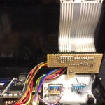
Having written the code on the mbed emulating a ZX81 I gave the Raspberry Pi a go in OS-less mode (Bare Metal) so after powerup the PI boots straight into the ZX81 emulator.
First steps were in assembler, then moved on to C


Having written the code on the mbed emulating a ZX81 I gave the Raspberry Pi a go in OS-less mode (Bare Metal) so after powerup the PI boots straight into the ZX81 emulator.
First steps were in assembler, then moved on to C
This small project spun out of control after I got (almost) componentless fullgraphic VGA output working on a mbed LPC1768 module.
The mbed module is connected with only a few resistors to a VGA monitor displaying 640×480/640×240 in monochrome.
On the mbed site I found a project from Ivo van Poorten whom had created a 80×25 VGA monochrome text output from the mbed.
Tinkering with the code and some serious datasheet reading I managed to turn it into a full 640×480 monochrome bitmap VGA output. The bitshifter (I2S output) is running in full-DMA mode so there is hardly any impact on the CPU speed.
Alas it is only monochrome so what could you use it for?
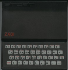
Hmm, my first computer was a Sinclair ZX81 which did only monochrome. Could the mbed emulate such a system ?
First step Z80 emulation, having tried several ‘off-the-shelf’ Z80 emulator code bases I decided to rewrite/modify the leanest Z80 emulator I could find so it would compile to the optimal and smallest C code on the mbed . Next step, inserting the ZX81 ROM code and get some picture on the screen. After that I inserted SD card storage code, added PS2 keyboard input and finally with the left-over IO pins I managed to connect an original ZX81 keyboard membrane to the mbed too, add zxpand joystick compatibility and did a rudimentary AY-3-8910 sound chip emulator in software too.
All these things work without extra logic or such, just some diodes and resistors.
To be true to the original I built the whole system into the original casing of a ZX81.
The software was modified quite some times, it even includes a Z80 disassembler, register viewer, hexdumper and the full ZX81 manual.


This is the speedometer replacement I made for my trusty old VW Beetle (1973). The main processor (another DS5000), display and indicators are inside the original speedometer housing. The analog to digital converter is in a separate aluminium box under the hood.
The speed sensor is made of a sensorwheel from a PC mouse and is driven by the original speedometer cable in a 1:1 ratio to the front wheel revolutions. Each revolution results in 45 ‘ticks’ on the timer input.
By calculating the circumference of the wheel the speed and distance calculations could be determined. With the current wheel size every 100 meters there are 2222 ticks on the timer. The display updates ones every second so the speed indicator is nice and steady during driving.
I also had the opportunity to add a ‘daytrip’ counter along with the total amount of kilometers driven, a clock, voltage indicator and of course the fuel indicator.
Since the DS5000 has battery backed SRAM as its main storage the clock, distance and daytrip values are not lost when the system is switched off.
The fuel indicator in the original speedometer is attached to a fuelsender which ‘ burned out’ several times in my VW due to the old stabilizers intermittent failure.A common problem with the Beetle
In the new setup the current through the sender is kept at a constant value and the amount of fuel is determined by reading the voltage across the sender so hopefully the sender will last a lot longer now.
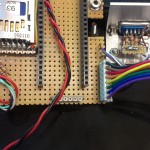
Programming and ‘dry run’ on the bench:

Inside the car


The ‘Bootsplash’ I added which is shown briefly during ‘ignition on’ (camera was a tad bit slow)

The display is a 120×64 backlit LCD
The external (I2C driven) A/D converter box (note: the TEMP and RPM inputs are not yet used)

Here is a link to the C source of the system:
Future plans include a color LCD, a ‘rev counter’ and maybe some more indicators for other functions.
High end audio fans always talk about how Tube Amplifiers sound better than their semiconductor counterparts. Well I know the theory about electron tubes and I like listening to music.. hmm..
Since I never had built an electronic device with electron tubes I decided to build my own set of ‘high-end’ amplifiers.
There are many circuit diagrams for DIY tube amplifiers to be found but in a an old Radio Electronics magazine (from 1962!) I found an article stating: ‘an audio amplifier of exceptional quality’..
The specifications mentioned a frequency range from 20 to 100000 Hz (yes, 100 kHz). That is way beyond the audible range.
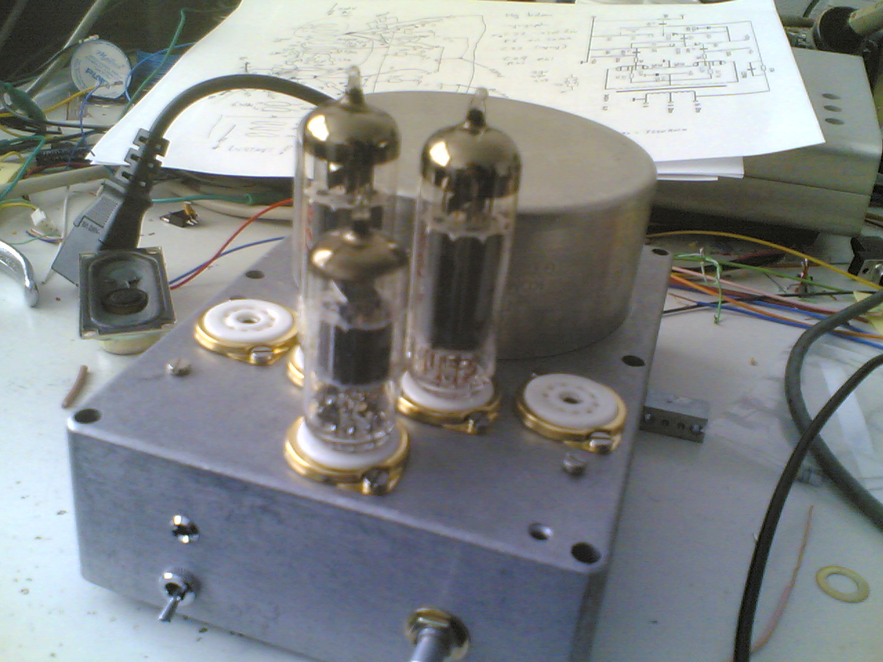
The circuit was not very difficult, two EL84’s and a ECF86 tube. The latter is not very common in audio equipment but I gave it a go.
First I had to find the components. The necessary tubes were found on a website specialising in new tubes for Guitar Amplifiers and such. For the capacitors and resistors I used high quaility modern day equivalents.
The original transformers are no longer in production so I replaced them by high-quality Amplimo toroid transformers. The output transformer was designed by Menno van der Veen and even though the frequency range is according to specifications ‘only’ up to 50 kHz, it would be more than adequate.
By building two seperate mono amplifiers (aka monoblocks) I have no problem with crosstalk between the channels.
Later on I have built a Phono pre-amplifier with tubes and a set of very special pyramid loudspeakers.

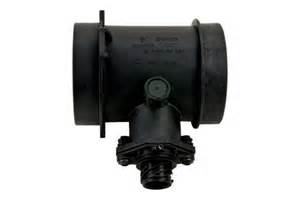
To achieve faster throttle response and less air resistance we replaced a standard Air Mass Volume sensor like this:

in a Porsche 911 (964 3.6L engine) by a newer type Bosch Air Flow sensor (HFC unit) like this:
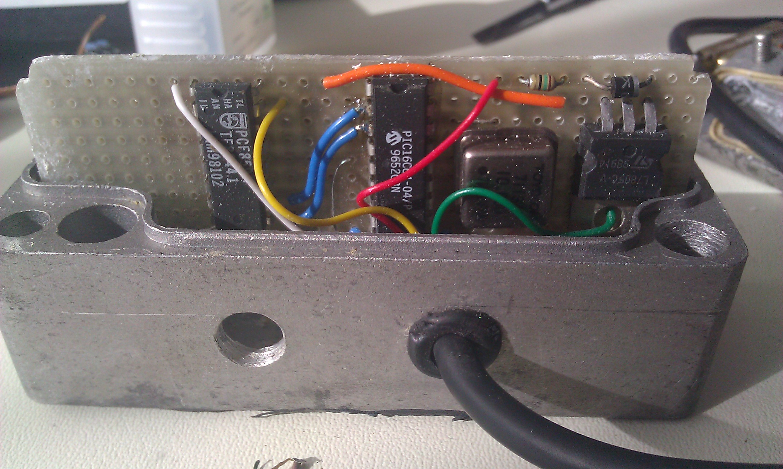
Unfortunately the output signals don’t match and at that moment reprogramming the Motronic was not an option. So I decided to make a programmable converter which took the signal from the HFC unit and emitted a signal the Motronic would accept as valid input.
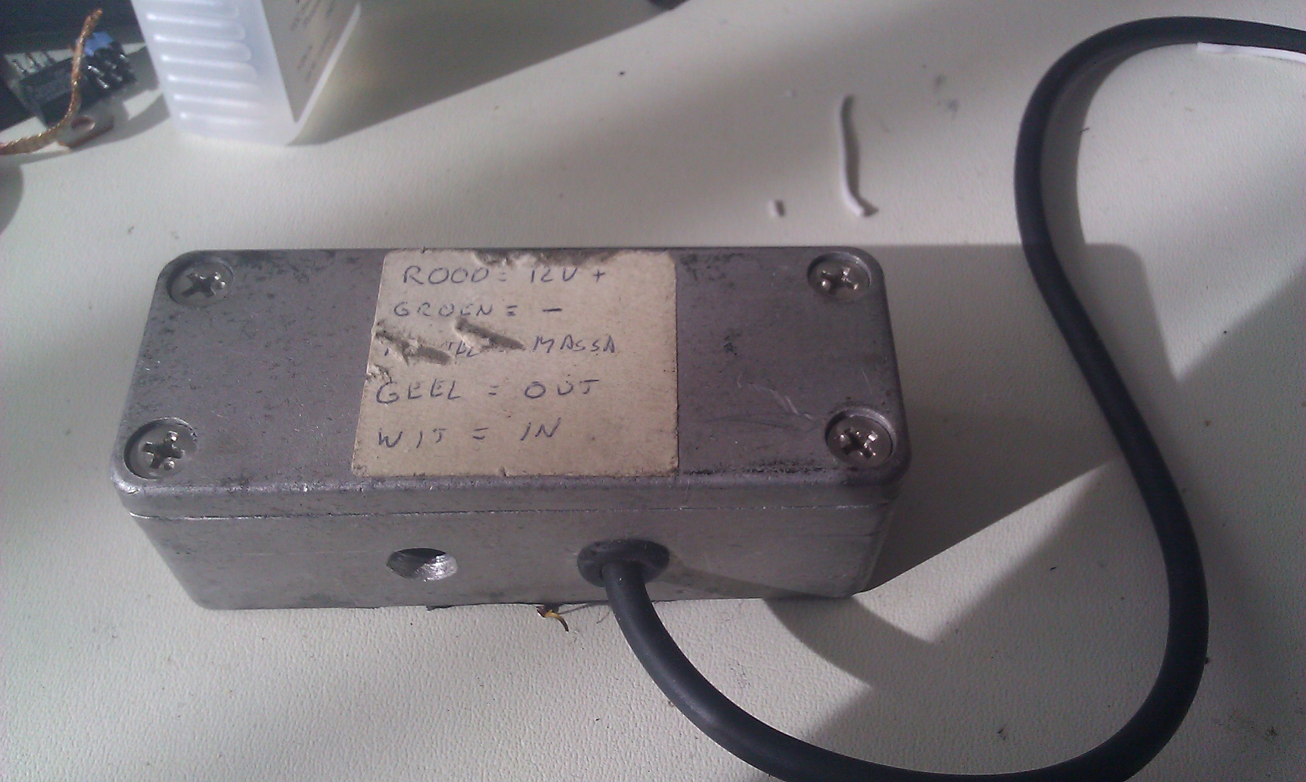
The converter unit was made with a PIC16F84 microcontroller connected to a Philips I2C PCF8591 8 bit AD/DA converter mounted in a sturdy metal box.


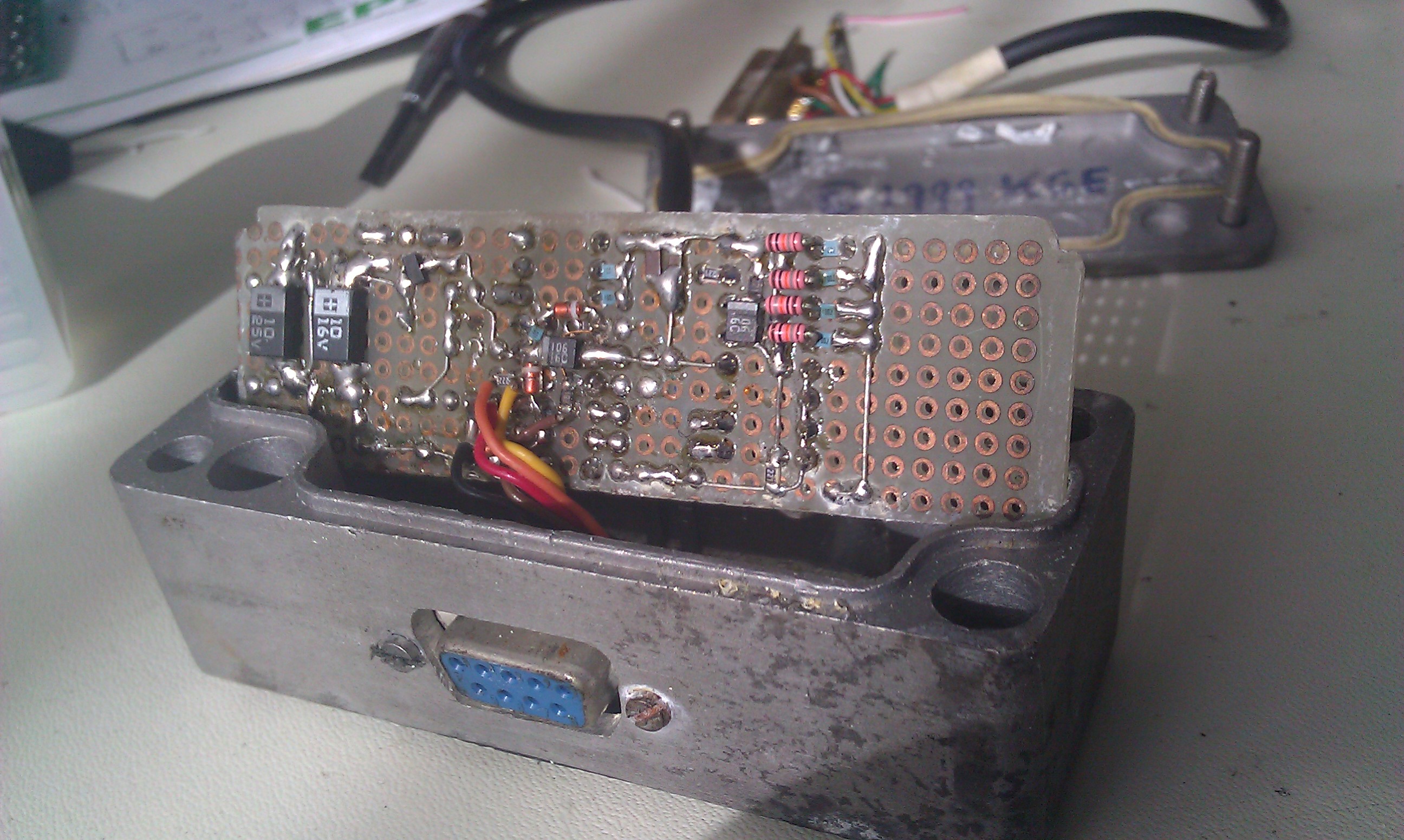
With a laptop and some special written software (with Xforms under Linux) the curve for the signal was adjustable by mouse and after some hours of tweaking, CO measuring and testdriving the best settings were found.
