For work I needed a programmable interval timer capable of generating pulses of a pre-determined length and interval.
Having ordered a few Arduino nano clones some time ago I could put them to good use now.
I set up some simple design rules:
- adjustable pulse length
- adjustable interval time
- two outputs minimum
- display
- pushbutton control
- 24V DC power supply
- potential free output contacts
- short circuit and polarity reversal proof
I gathered some components from the junk box like an LCD (from an defunct Espresso machine), some pushbuttons, relays and some screwterminals (from a defunct alarm board) and an empty prototype board.
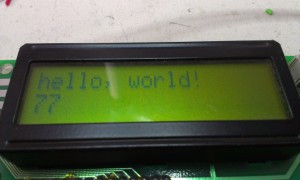
The display proved the first hurdle: It looked like and ordinary 16×2 LCD bit it had only 13 pins instead of the more usual 14 or 16 pins. The display was custom made for the espressomachine factory.
After some checking with the multimeter it seemed that the contrast pin was not available and the backlight was permanently connected to the supply pins. The controller proved to be compatible with the standard HD64810 controller. So after some re-wiring attempts I got this:
Succes!
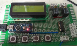
Next step: add some buttons, the relays (small 24V DC with a single change-over contact), a relay driver (ULN2003), polyfuses (500mA 75V, to keep the current of the outputs within limits) and the screwterminals:
In the picture above the nano board is powered by the USB (programming) cable. Later on the board is supposed to be run from the standard industrial 24 Volt DC.
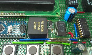
Linear voltage regulation (like with a 7805 regulator) was out of the question because the huge voltage difference and the accompanying energy dissipation. So I opted for a LM2575 switch mode regulator. The chip I scavenged from an old Deltakabel modem was carefully ‘extracted’ along with a piece of the original PCB to be used as carrierboard , cut to size (with a small hacksaw) and ‘grafted’ onto my prototyping board:
The square block (PE-52626) is the original inductor from the modemboard connected to the LM2575. The two electrolytic capacitors keep the in- and output voltage smooth. On the right you can see the relay driver chip ULN2003, it has 7 open collector outputs, two of these are used to drive the relays, three other outputs are connected to the screwterminals on the far right of the board along with a ground and +24V terminal. These are reserved for future use.
Reverse polarity protection of the 24V DC input is done by a single diode (1N4007 or such)
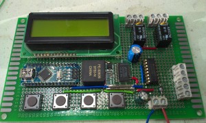
The complete board now looked like this:
Now I only needed some code to drive it all…
The four buttons (from left to right) are used like this:
- FUNCTION
- DOWN
- UP
- START/STOP
The function button steps through the following options:
- Interval time
- Delay time output 1
- Length output 1
- Delay time output 2
- Length output 2
The timing is set in 0.1 sec (100ms) steps. Delay will pause the activation of the output so it is possible to activate output 2 after output 1 but within the pulse length of output 1 or vice versa. Setting the Length of output 1 or 2 to zero disable the output.
With the start/stop button the sequence is started.
The software is written in just an hour so it is quite rough and has undoubtedly bugs but the board has already performed just as it should.
This is the current Arduino source code, no warranties…
/*
 This sketch creates a double interval timer
 by Gert van der Knokke (c)2016 KGE V0.3

 The circuit:
 * LCD RS pin to digital pin 12
 * LCD Enable pin to digital pin 11
 * LCD D4 pin to digital pin 5
 * LCD D5 pin to digital pin 4
 * LCD D6 pin to digital pin 3
 * LCD D7 pin to digital pin 2
 * LCD R/W pin to ground
 * 10K resistor:
 * ends to +5V and ground
 * wiper to LCD VO pin (pin 3)
 */

// include the library code:
#include <LiquidCrystal.h>
#include <avr/eeprom.h>

const int rel1 = 6;
const int rel2 = 7;

const int dout11 = 8;
const int dout12 = 9;
const int dout13 = 10;

char regel1[17];
char regel2[17];

struct userconfig {
  int length1;
  int length2;
  int delay1;
  int delay2;
  int interval;
}
config;

int runflag;
int t;

int button1_pressed = 0;
int button2_pressed = 0;
int button3_pressed = 0;
int button4_pressed = 0;

int function =0;
const int max_function=5;

unsigned long currentMillis;

// initialize the library with the numbers of the interface pins
LiquidCrystal lcd(12, 11, 5, 4, 3, 2);

void setup() {
  // set up the LCD's number of columns and rows:
  lcd.begin(16, 2);
  // Print a message to the LCD.
  lcd.print("Interval timer");
  lcd.setCursor(0, 1);
  lcd.print("V0.3 (C)KGE 2016");

  // analog inputs a0-a3 as inputs with pullup
  pinMode(14, INPUT_PULLUP);
  pinMode(15, INPUT_PULLUP);
  pinMode(16, INPUT_PULLUP);
  pinMode(17, INPUT_PULLUP);

  pinMode(rel1, OUTPUT);
  digitalWrite(rel1,LOW);
  pinMode(rel2, OUTPUT);
  digitalWrite(rel2,LOW);
  pinMode(dout11, OUTPUT);
  digitalWrite(dout11,LOW);
  pinMode(dout12, OUTPUT);
  digitalWrite(dout12,LOW);
  pinMode(dout13, OUTPUT);
  digitalWrite(dout13,LOW);

  config.delay1=0;
  config.delay2=5;
  config.length1=10;
  config.length2=10;
  config.interval=20;
  eeprom_read_block((void*)&config, (void*)0, sizeof(config));
  runflag=0;
  t=0;
  currentMillis=millis();
  while ((millis()-currentMillis)<2000);
}


void check_buttons()
{
  // function button pressed
  if ((digitalRead(14)==0) && (button1_pressed==0))
  {
    button1_pressed=1;
    if (function<max_function) function++;
    else function=0;
  }

  // function button released
  if ((digitalRead(14)==1) && (button1_pressed==1))
  {
    button1_pressed=0;
  }

  //-----------------------------------------------------

  // plus button pressed
  if ((digitalRead(16)==0) && (button3_pressed==0))
  {
    button3_pressed=1;

    switch( function)
    {
    case 0:
      if (config.interval<10000) config.interval++;
      break;
    case 1:
      if (config.delay1 < (config.interval-config.length1)) config.delay1++;
      break;
    case 2:
      if (config.length1 < (config.interval-config.delay1)) config.length1++;
      break;
    case 3:
      if (config.delay2 < (config.interval-config.length2)) config.delay2++;
      break;
    case 4:
      if (config.length2 < (config.interval-config.delay2)) config.length2++;
      break;
    }
  }

  // plus button released
  if ((digitalRead(16)==1) && (button3_pressed==1))
  {
    button3_pressed=0;
    // write config to EEPROM if YES/+ is released and in save settings function
    if (function==5)
    {
      eeprom_write_block((const void*)&config, (void*)0, sizeof(config));
      function=0;
    }
  }

  // minus button pressed
  if ((digitalRead(15)==0) && (button2_pressed==0))
  {
    button2_pressed=1;

    switch( function)
    {
    case 0:
      if (config.interval>0) config.interval--;
      break;
    case 1:
      if (config.delay1>0) config.delay1--;
      break;
    case 2:
      if (config.length1>0) config.length1--;
      break;
    case 3:
      if (config.delay2>0) config.delay2--;
      break;
    case 4:
      if (config.length2>0) config.length2--;
      break;
    }
  }

  // minus button released
  if ((digitalRead(15)==1) && (button2_pressed==1))
  {
    button2_pressed=0;
    if (function==5) function=0;
  }


  // start/stop button pressed
  if ((digitalRead(17)==0) && (button4_pressed==0))
  {
    button4_pressed=1;
    if (runflag==1)
    {
      runflag=0;
    }
    else
    {
      t=0;
      function=0;
      runflag=1;
    }
  }

  // start/stop button released
  if ((digitalRead(17)==1) && (button4_pressed==1))
  {
    button4_pressed=0;
  }


}

void check_relay1()
{
  if (config.length1==0)
  {
    digitalWrite(rel1,LOW);
    return;
  }

  if ((t>=config.delay1) && (t<(config.length1+config.delay1)))
  {
    digitalWrite(rel1, HIGH);
  }
  else
  {
    digitalWrite(rel1,LOW);
  }
}

void check_relay2()
{
  if (config.length2==0)
  {
    digitalWrite(rel2,LOW);
    return;
  }

  if ((t>=config.delay2) && (t<(config.length2+config.delay2)))
  {
    digitalWrite(rel2, HIGH);
  }
  else
  {
    digitalWrite(rel2,LOW);
  }
}

void loop() {
  float f;
  currentMillis=millis();

  if (t>config.interval) t=0;

  //  lcd.setCursor(0, 0);

  check_buttons();

  if (runflag)
  {
    check_relay1();
    check_relay2();
    // print the number of seconds since reset:
    sprintf(regel1,"Time:   %5d.%1ds",t/10,t%10);
    lcd.setCursor(0,0);
    lcd.print(regel1);
    // set the cursor to column 0, line 1
    // (note: line 1 is the second row, since counting begins with 0):
    lcd.setCursor(0, 1);
    sprintf(regel2,"<-- running  -->");

    lcd.print(regel2);
    t=t+1;
  }
  else
  {
    digitalWrite(rel1,LOW);
    digitalWrite(rel1,LOW);
    sprintf(regel2,">-- stopped  --<");

    switch( function)
    {                       //  0123456789ABCDEF
    case 0:
      sprintf(regel1,"Interval:%4d.%1ds",config.interval/10,config.interval%10);
      break;
    case 1:
      sprintf(regel1," Delay 1:%4d.%1ds",config.delay1/10,config.delay1%10);
      break;
    case 2:
      sprintf(regel1,"Length 1:%4d.%1ds",config.length1/10,config.length1%10);
      break;
    case 3:
      sprintf(regel1," Delay 2:%4d.%1ds",config.delay2/10,config.delay2%10);
      break;
    case 4:
      sprintf(regel1,"Length 2:%4d.%1ds",config.length2/10,config.length2%10);
      break;
    case 5:
      sprintf(regel1," Save settings? ");
      sprintf(regel2,"     NO  YES    ");
      break;
    }
    lcd.setCursor(0, 0);
    lcd.print(regel1);
    lcd.setCursor(0, 1);
    lcd.print(regel2);

  }
  while ((millis()-currentMillis)<100);

}
Sorry for the horrible indentation, WP messes this up quite bad..
Here is a downloadable version: intervaltimer (note: in order to use it with the Arduino IDE you need to rename this to intervaltimer.ino)
Future enhancements will be:
saving the settings in EEPROMdone- controlling the extra open collector outputs
- using the small ‘graphic’ part of the display
timing settings in a more readable form instead of just a number of 100ms steps- limiting ranges on settings based upon interval timing


