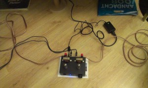
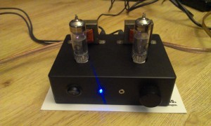
This project started after getting an old schoolproject from a friend. A metal chassis with a single ECL86 tube, a power transformer and a small Muvolett (Amroh) 7044 output transformer. Intrigued by the simplicity of this amplifier I decided to rebuild the amplifier into a small stereo amplifier.
First step: getting a second Muvolett output transformer. On ‘circuitsonline’ I found by coincidence someone offering just such a transformer. After some emails and bidding I got the second transformer (new old stock, in box with waranty card…)
Next step: getting some new tubes as this ECL86 was quite old and hard to get I decided to get two new ECL82 instead. These are functionally the same: a triode and a pentode in a single glass envelope.
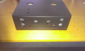
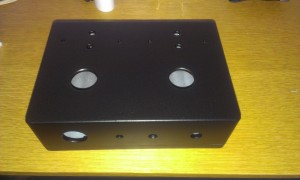
Step three: drilling and milling.. As a fond user of die-cast aluminium enclosures the choice was quickly made. After drilling, sanding, filling and painting the case came out like this:
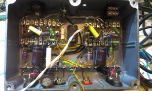
Step four: adding the components.
Wiring and mounting is on nostalgic style solder terminal boards. I used PCB type tube sockets mounted on small rivets on those boards. Some spacers between the case and the boards make the tube undersides flush with the top of the case. The circuit I used is a mix of some diagrams found on the web and a lot of experimentation by me.
Step five: power supply… Those ECL82 need about 200 Volts on their anodes to work properly but I did not want to use a bulky humming transformer. I decided to use a switch mode powersupply (SMPS) but these are not readily available.
My first powersupply setup was based on a project found on the web where an electronic halogen lamp transformer was modified. This seemed a nice alternative and I tried modifying a 20-40W 12V electronic halogen transformer by removing some of the 12V windings to get 6.3 Volt and adding 4 parallell wound wires (which were put in series later on) to generate 200 Volts. This setup worked reasonably well but since these devices have no regulation, the voltages varied wildly during startup and I even had to tame the +200V with a zener and a shunt resistor to prevent the capacitors from blowing up during the time the tubes were not conducting yet. There also was a nasty high frequency interference induced into the anode output caused by me using the AC voltage directly from the electronic transformer. Even after a lot of filtering and such the electronic transformer could just keep up with the needed power.
Another supply was needed, one that could run on a single external low voltage DC supply (maybe a laptop adapter) to keep mains ‘hum’ out of the box and one that could power the filaments and the high voltage needed for the anode supply.
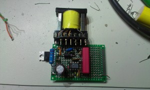
By putting the filaments of the two ECL82 in series the supply was set at 12 Volts. A dedicated DC-DC converter was made from some scrap parts and a SMPS controller called UC3843. After some tweaking and tailoring the circuit from the datasheet to match the transformer, the converter supplies a steady 200 Volts at about 75 milliAmpere. Efficiency is good, the power FET on the left is mounted (isolated) to the bottom of the case and this acts as an excellent heatsink for the (small) amount of wasted energy.
Total power consumption is about 30 Watts total (filaments and anode supply) which translates to 2.5 Amperes at 12 Volt. I found a 12 Volt 4 Ampere supply from a defunct Wyse terminal in the junkbox and it can deliver this amount of energy with ease.
The sound.. Well it sounds great given the fact that these small output transformers deliver only about 3 Watts true power. It is a bit thin on the low frequencies but probably also due to this type of transformer. Maybe some tweaking of the tube circuit can improve a bit more.
All in all I am pleased with the result.
