Category Archives: Uncategorized

Exidy Sorcerer emulator

What to do with an ancient but perfectly functional IBM terminal keyboard?

Well, turn it into a full featured Exidy Sorcerer computer..

Inside the keyboard was enough space to add a mbed LCP1768 module, a (micro)SD card reader and a VGA port. The emulator is still work in progress but it already runs much of the Exidy software.

The space available

Universal Interval Timer (2016)

For work I needed a programmable interval timer capable of generating pulses of a pre-determined length and interval.

Having ordered a few Arduino nano clones some time ago I could put them to good use now.

I set up some simple design rules:

  • adjustable pulse length
  • adjustable interval time
  • two outputs minimum
  • display
  • pushbutton control
  • 24V DC power supply
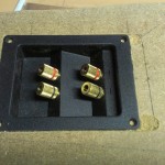
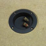
  • potential free output contacts
  • short circuit and polarity reversal proof

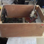
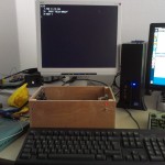
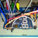
I gathered some components from the junk box like an LCD (from an defunct Espresso machine), some pushbuttons, relays and some screwterminals (from a defunct alarm board) and an empty prototype board.

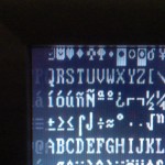
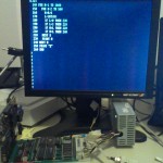
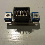
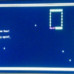
The display proved the first hurdle: It looked like and ordinary 16×2 LCD bit it had only 13 pins instead of the more usual 14 or 16 pins. The display was custom made for the espressomachine factory.

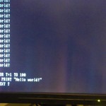
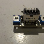
After some checking with the multimeter it seemed that the contrast pin was not available and the backlight was permanently connected to the supply pins. The controller proved to be  compatible with the standard HD64810 controller. So after  some re-wiring attempts I got this:
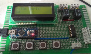
2016-01-28 11.03.44

Succes!

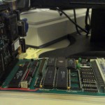
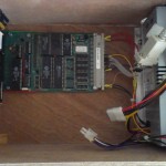
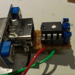
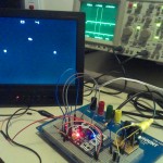
Next step: add some buttons, the relays (small 24V DC with a single change-over contact), a relay driver (ULN2003), polyfuses (500mA 75V, to keep the current of the outputs within limits) and the screwterminals:

2016-01-28 11.03.07

In the picture above the nano board is powered by the USB (programming) cable. Later on the board is supposed to be run from the standard industrial 24 Volt DC.

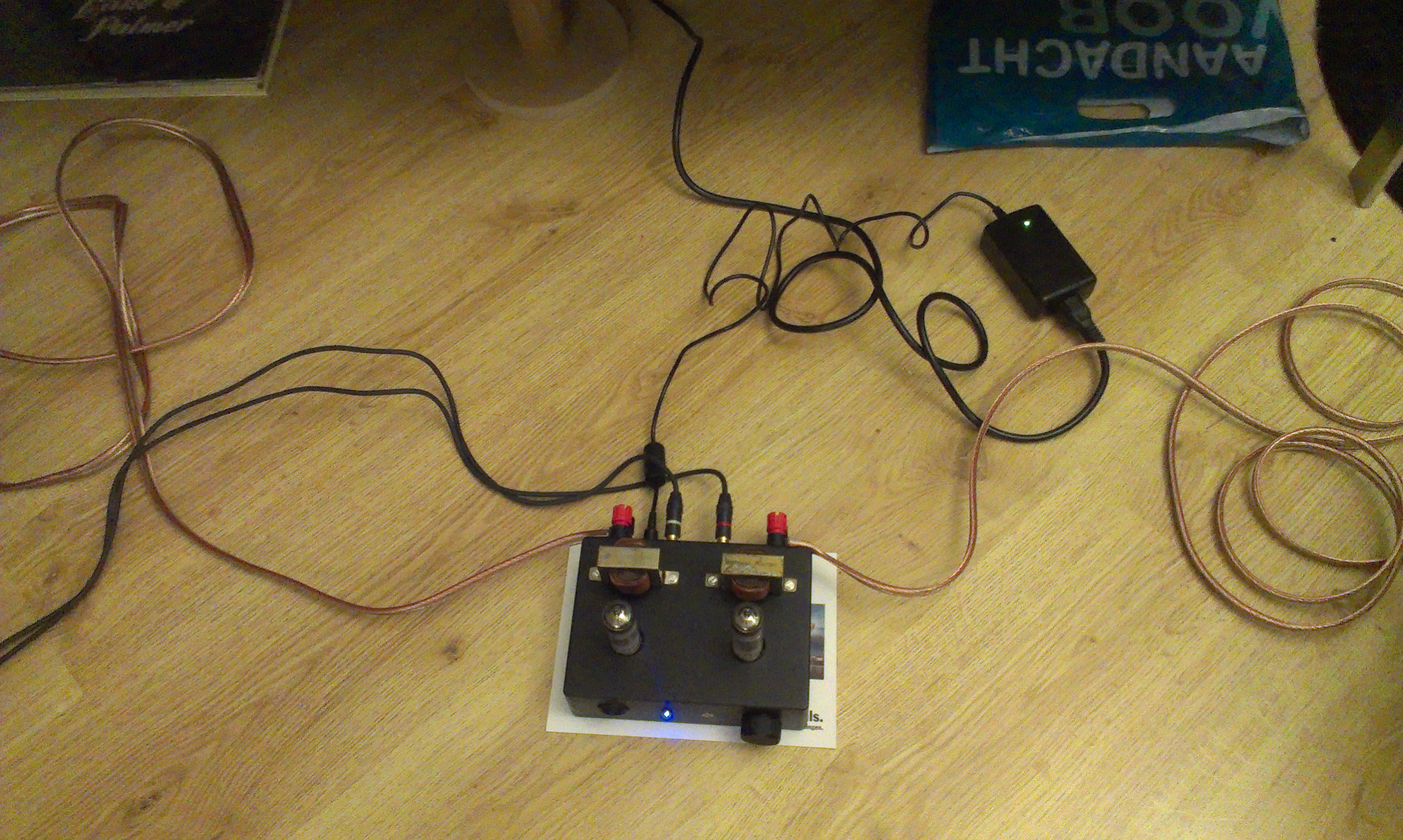
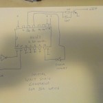
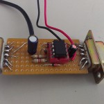
Linear voltage regulation (like with a 7805 regulator) was out of the question because the huge voltage difference and the accompanying energy dissipation. So I opted for a LM2575 switch mode regulator. The chip I scavenged from an old Deltakabel modem was carefully ‘extracted’ along with a piece of the original PCB to be used as carrierboard , cut to size (with a small hacksaw) and ‘grafted’ onto my prototyping board:

2016-01-28 11.56.19

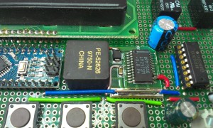
The square block (PE-52626) is the original inductor from the modemboard connected to the LM2575. The two electrolytic capacitors keep the in- and output voltage smooth. On the right you can see the relay driver chip ULN2003, it has 7 open collector outputs, two of these are used to drive the relays, three other outputs are connected to the screwterminals on the far right of the board along with a ground and +24V terminal. These are reserved for future use.

Reverse polarity protection of the 24V DC input is done by a single diode (1N4007 or such)

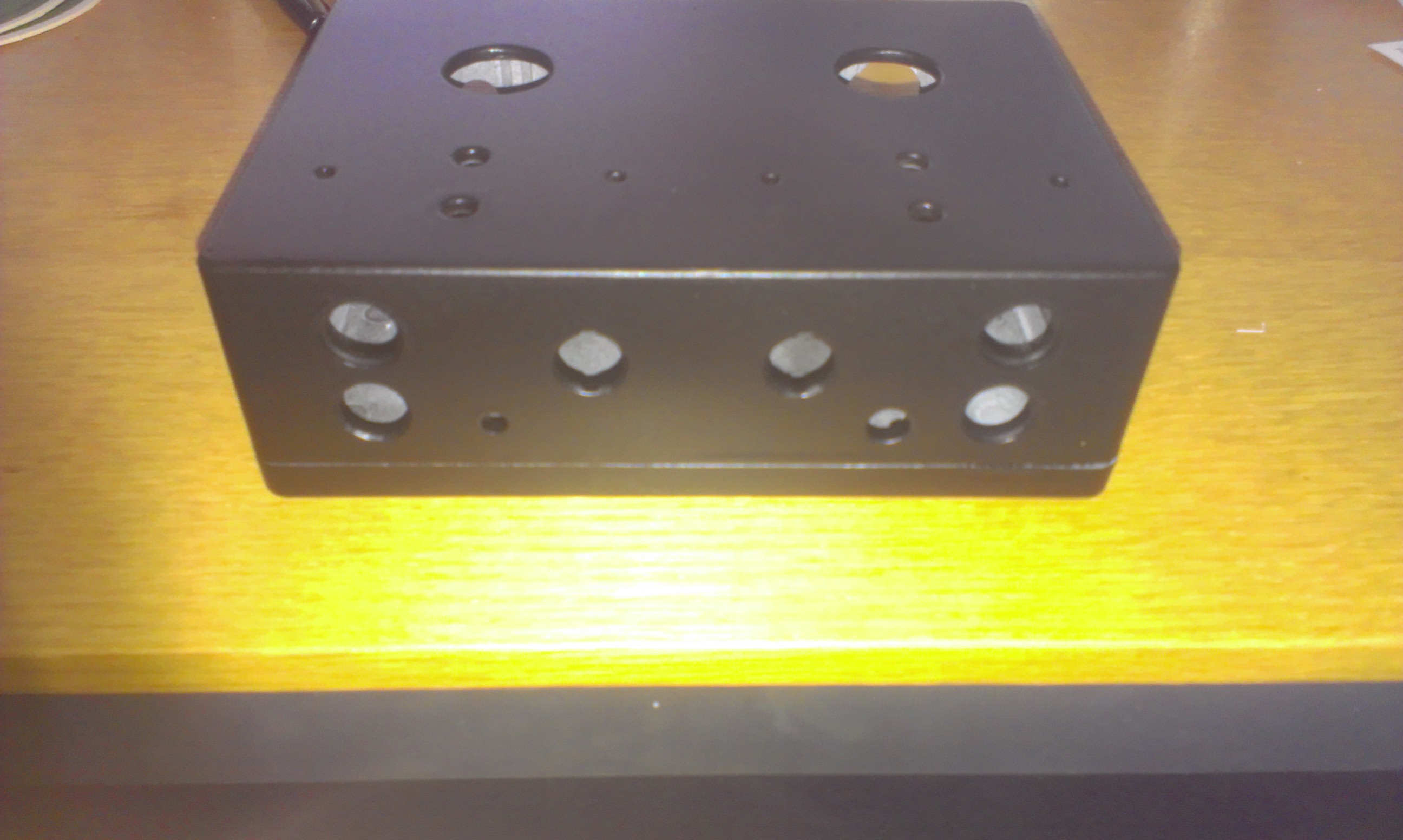
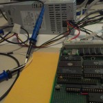
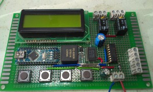
The complete board now looked like this:

2016-01-28 11.56.24

Now I only needed some code to drive it all…

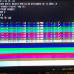
The four buttons (from left to right) are used like this:

  1. FUNCTION
  2. DOWN
  3. UP
  4. START/STOP

The function button steps through the following options:

  • Interval time
  • Delay time output 1
  • Length output 1
  • Delay time output 2
  • Length output 2

The timing is set  in 0.1 sec (100ms) steps. Delay will pause the activation of the output so it is possible to activate output 2 after output 1 but within the pulse length of output 1 or vice versa. Setting the Length of output 1 or 2 to zero disable the output.

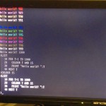
With the start/stop button the sequence is started.

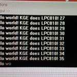
The software is written in just an hour so it is quite rough and has undoubtedly bugs but the board has already performed just as it should.

This is the current Arduino source code, no warranties…

/*
 This sketch creates a double interval timer
 by Gert van der Knokke (c)2016 KGE V0.3
 
 The circuit:
 * LCD RS pin to digital pin 12
 * LCD Enable pin to digital pin 11
 * LCD D4 pin to digital pin 5
 * LCD D5 pin to digital pin 4
 * LCD D6 pin to digital pin 3
 * LCD D7 pin to digital pin 2
 * LCD R/W pin to ground
 * 10K resistor:
 * ends to +5V and ground
 * wiper to LCD VO pin (pin 3)
 */

// include the library code:
#include <LiquidCrystal.h>
#include <avr/eeprom.h>

const int rel1 = 6;
const int rel2 = 7;

const int dout11 = 8;
const int dout12 = 9;
const int dout13 = 10;

char regel1[17];
char regel2[17];

struct userconfig {
  int length1;
  int length2;
  int delay1;
  int delay2;
  int interval;
} 
config;

int runflag;
int t;

int button1_pressed = 0;
int button2_pressed = 0;
int button3_pressed = 0;
int button4_pressed = 0;

int function =0;
const int max_function=5;

unsigned long currentMillis;

// initialize the library with the numbers of the interface pins
LiquidCrystal lcd(12, 11, 5, 4, 3, 2);

void setup() {
  // set up the LCD's number of columns and rows: 
  lcd.begin(16, 2);
  // Print a message to the LCD.
  lcd.print("Interval timer");
  lcd.setCursor(0, 1);
  lcd.print("V0.3 (C)KGE 2016");

  // analog inputs a0-a3 as inputs with pullup
  pinMode(14, INPUT_PULLUP);
  pinMode(15, INPUT_PULLUP);
  pinMode(16, INPUT_PULLUP);
  pinMode(17, INPUT_PULLUP);

  pinMode(rel1, OUTPUT);
  digitalWrite(rel1,LOW);
  pinMode(rel2, OUTPUT);
  digitalWrite(rel2,LOW);
  pinMode(dout11, OUTPUT);
  digitalWrite(dout11,LOW);
  pinMode(dout12, OUTPUT);
  digitalWrite(dout12,LOW);
  pinMode(dout13, OUTPUT);
  digitalWrite(dout13,LOW);

  config.delay1=0;
  config.delay2=5;
  config.length1=10;
  config.length2=10;
  config.interval=20;
  eeprom_read_block((void*)&config, (void*)0, sizeof(config));
  runflag=0;
  t=0;
  currentMillis=millis();
  while ((millis()-currentMillis)<2000);
}


void check_buttons()
{
  // function button pressed
  if ((digitalRead(14)==0) && (button1_pressed==0))
  {
    button1_pressed=1;
    if (function<max_function) function++; 
    else function=0;
  }

  // function button released
  if ((digitalRead(14)==1) && (button1_pressed==1))
  {
    button1_pressed=0;
  }

  //-----------------------------------------------------

  // plus button pressed
  if ((digitalRead(16)==0) && (button3_pressed==0))
  {
    button3_pressed=1;

    switch( function)
    {
    case 0: 
      if (config.interval<10000) config.interval++;
      break;
    case 1: 
      if (config.delay1 < (config.interval-config.length1)) config.delay1++;
      break;
    case 2: 
      if (config.length1 < (config.interval-config.delay1)) config.length1++;
      break;
    case 3: 
      if (config.delay2 < (config.interval-config.length2)) config.delay2++;
      break;
    case 4: 
      if (config.length2 < (config.interval-config.delay2)) config.length2++;
      break;
    }
  }

  // plus button released
  if ((digitalRead(16)==1) && (button3_pressed==1))
  {
    button3_pressed=0;
    // write config to EEPROM if YES/+ is released and in save settings function
    if (function==5) 
    { 
      eeprom_write_block((const void*)&config, (void*)0, sizeof(config));
      function=0;
    }
  }

  // minus button pressed
  if ((digitalRead(15)==0) && (button2_pressed==0))
  {
    button2_pressed=1;

    switch( function)
    {
    case 0: 
      if (config.interval>0) config.interval--;
      break;
    case 1: 
      if (config.delay1>0) config.delay1--;
      break;
    case 2: 
      if (config.length1>0) config.length1--;
      break;
    case 3: 
      if (config.delay2>0) config.delay2--;
      break;
    case 4: 
      if (config.length2>0) config.length2--;
      break;
    }
  }

  // minus button released
  if ((digitalRead(15)==1) && (button2_pressed==1))
  {
    button2_pressed=0;
    if (function==5) function=0;
  }


  // start/stop button pressed
  if ((digitalRead(17)==0) && (button4_pressed==0))
  {
    button4_pressed=1;
    if (runflag==1)
    { 
      runflag=0;
    }
    else
    {
      t=0;
      function=0;
      runflag=1;
    }
  }

  // start/stop button released
  if ((digitalRead(17)==1) && (button4_pressed==1))
  {
    button4_pressed=0;
  }


}

void check_relay1()
{
  if (config.length1==0)
  {
    digitalWrite(rel1,LOW);
    return;
  }

  if ((t>=config.delay1) && (t<(config.length1+config.delay1)))
  { 
    digitalWrite(rel1, HIGH);
  }
  else
  {
    digitalWrite(rel1,LOW);
  }
}

void check_relay2()
{
  if (config.length2==0)
  {
    digitalWrite(rel2,LOW);
    return;
  }

  if ((t>=config.delay2) && (t<(config.length2+config.delay2))) 
  { 
    digitalWrite(rel2, HIGH);
  }
  else
  {
    digitalWrite(rel2,LOW);
  }
}

void loop() {
  float f;
  currentMillis=millis();

  if (t>config.interval) t=0;

  //  lcd.setCursor(0, 0);

  check_buttons();

  if (runflag)
  {
    check_relay1();
    check_relay2();
    // print the number of seconds since reset:
    sprintf(regel1,"Time:   %5d.%1ds",t/10,t%10);
    lcd.setCursor(0,0);
    lcd.print(regel1);
    // set the cursor to column 0, line 1
    // (note: line 1 is the second row, since counting begins with 0):
    lcd.setCursor(0, 1);
    sprintf(regel2,"<-- running  -->");

    lcd.print(regel2);
    t=t+1;
  }
  else
  {
    digitalWrite(rel1,LOW);
    digitalWrite(rel1,LOW);
    sprintf(regel2,">-- stopped  --<");

    switch( function)
    {                       //  0123456789ABCDEF
    case 0: 
      sprintf(regel1,"Interval:%4d.%1ds",config.interval/10,config.interval%10);
      break;
    case 1: 
      sprintf(regel1," Delay 1:%4d.%1ds",config.delay1/10,config.delay1%10);
      break;
    case 2: 
      sprintf(regel1,"Length 1:%4d.%1ds",config.length1/10,config.length1%10);
      break;
    case 3: 
      sprintf(regel1," Delay 2:%4d.%1ds",config.delay2/10,config.delay2%10);
      break;
    case 4: 
      sprintf(regel1,"Length 2:%4d.%1ds",config.length2/10,config.length2%10);
      break;
    case 5: 
      sprintf(regel1," Save settings? ");
      sprintf(regel2,"     NO  YES    ");
      break;
    }
    lcd.setCursor(0, 0);
    lcd.print(regel1);
    lcd.setCursor(0, 1);
    lcd.print(regel2);

  }
  while ((millis()-currentMillis)<100);  

}

Sorry for the horrible indentation, WP messes this up quite bad..

Here is a downloadable version: intervaltimer (note: in order to use it with the Arduino IDE you need to rename this to intervaltimer.ino)

Future enhancements will be:

  • saving the settings in EEPROM done
  • controlling the extra open collector outputs
  • using the small ‘graphic’ part of the display
  • timing settings in a more readable form instead of just a number of 100ms steps
  • limiting ranges on settings based upon interval timing

Mini stereo SE tube amp (2015)

This project started after getting an old schoolproject from a friend. A metal chassis with a single ECL86 tube, a power transformer and a small Muvolett (Amroh) 7044 output transformer. Intrigued by the simplicity of this amplifier I decided to rebuild the amplifier into a small stereo amplifier.

First step: getting a second Muvolett output transformer. On ‘circuitsonline’ I found by coincidence someone offering just such a transformer. After some emails and bidding I got the second transformer (new old stock, in box with waranty card…)

Next step: getting some new tubes as this ECL86 was quite old and hard to get I decided to get two new ECL82 instead. These are functionally the same: a triode and a pentode in a single glass envelope.

Step three: drilling and milling.. As a fond user of die-cast aluminium enclosures the choice was quickly made. After drilling, sanding, filling and painting the case came out like this:

2015-01-04 09.24.512015-01-04 09.24.15

Step four: adding the components.

2015-01-25 17.16.26

Wiring and mounting is on nostalgic style solder terminal boards. I used PCB type tube sockets mounted on small rivets on those boards. Some spacers between the case and the boards make the tube undersides flush with the top of the case.  The circuit I used is a mix of some diagrams found on the web and a lot of experimentation by me.

Step five: power supply… Those ECL82 need about 200 Volts on their anodes to work properly but I did not want to use a bulky humming transformer. I decided to use a switch mode powersupply (SMPS) but these are not readily available.

My first powersupply setup was based on a project found on the web where an electronic halogen lamp transformer was modified. This seemed a nice alternative and I tried modifying a 20-40W 12V electronic halogen transformer by removing some of the 12V windings to get 6.3 Volt and adding 4  parallell wound wires (which were put in series later on) to generate 200 Volts. This setup worked reasonably well but since these devices have no regulation, the voltages varied wildly during startup and I even had to tame the +200V with a zener and a shunt resistor to prevent the capacitors from blowing up during the time the tubes were not conducting yet.  There also was a nasty high frequency interference induced into the anode output caused by me using the AC voltage directly from the electronic transformer. Even after a lot of filtering and such the electronic transformer could just keep up with the needed power.

Another supply was needed, one that could run on a single external low voltage DC supply (maybe a laptop adapter) to keep mains ‘hum’ out of the box and one that could power the filaments and the high voltage needed for the anode supply.

By putting the filaments of the two ECL82 in series the supply was set at 12 Volts. A dedicated DC-DC converter was made from some scrap parts and a SMPS controller called UC3843. After some tweaking and tailoring the circuit from the datasheet to match the transformer, the converter supplies a steady 200 Volts at about 75 milliAmpere.  Efficiency is good, the power FET on the left is mounted (isolated)  to the bottom of the case and this acts as an excellent heatsink for the (small) amount of wasted energy.

2015-02-01 16.59.21

Total power consumption is about 30 Watts total (filaments and anode supply) which translates to 2.5 Amperes at 12 Volt. I found a 12 Volt 4 Ampere supply from a defunct Wyse terminal in the junkbox and it can deliver this amount of energy with ease.

2015-02-01 20.47.37

The sound.. Well it sounds great given the fact that these small output transformers deliver only about 3 Watts true power. It is a bit thin on the low frequencies but probably also due to this type of transformer. Maybe some tweaking of the tube circuit can improve a bit more.

All in all I am pleased with the result.

2015-02-01 20.47.18

Testdriving the STM32F103C8T6 (2015)

Several suppliers, mostly from China, offer boards based on the STM32 series of ARM CPU’s

From a friend of mine I got a small board containing the STM32F103C8T6. It has 20k of SRAM, 64k of Flash memory, 37 IO pins and runs at clockspeeds of up to 76 MHz. It is a full blown Cortex M3 core with lots of possibilities and the whole board is available under $10

2014-12-22 22.37.30

That was the easy part, programming this thing is another…

You need a special programmer called the STLink-V2, originally from ST (of course) but lots of inexpensive copies can be found on Ebay. Ok, another weborder and some time later I had two of these programmers and tried attaching them to my laptop. Since I am running Linux I had to search for programming tools to use these devices. Also some udev rules are needed to have access to the USB programmer as a user.

A simple command line programming tool can be found at: https://github.com/texane/stlink

Now for some code…

Since I am a big fan of the mbed compiler and the mbed compiler supports one type of STM32, I tried making a simple ‘blinky’ type program and create a binary file to be uploaded to my board.

After selecting the STM32F108RB from the platforms page the compiler was setup.

The definition of the ‘myled’ IO pin needs to be changed to ‘PC_13’ and  the code compiled without problems into a nice ‘myblinky.bin’ file.

With the following command line I programmed the binary into the board:

st-flash write myblinky.bin 0x8000000

The blue led on the board started blinking! Succes!

I already had made some code for testing a large Vacuum Fluorescent Display (VFD) connected to the mbed LPC1768 board so I tried to move the code over to the STM32 and plug the board into my breadboard setup with the VFD.

Results are below:

2015-01-11 16.09.37 2015-01-11 16.09.30

Speed of this CPU is very good and power consumption is very low.

At the moment I am still struggling with a proper debug setup:

The LPC1768 mbed board simulates a serial port over USB and it is very easy to send debug information to a running terminal. The STlink-V2 programmer supports a special debug channel which can be connected to Linux GDB but it offers no serial channel and it cannot read the mbed binary file for source code level debugging. On the web I found several howto’s to setup a complete system using Eclipse as IDE and the gnu arm compiler toolkit but after ending up several times in ‘dependency hell‘ I gave up on that.


LED sign rebirth (2014)

Being a regular visitor of electronic flea-markets like the ‘Radio Onderdelen markt‘ at De Lichtmis in the Netherlands, I always seem to bring back something unusual. This time it was a LED sign, I have a kind of ‘display fetish’ thus this thing peaked my interest.

At home I discovered that there was very little to find about the whole device, there was a connector labeld ‘keyboard’ which had a small pcb with some rotary switches on it probably to select pre-programmed messages. After connecting power the sign showed no display. Disassembling revealed it was made by a company called Data Display somewhere in 1997 or such. The unit consists of two circuit boards: a controller and a LED part.

2014-09-27 16.13.05

The controller is a Hitachi 6303 8 bit microcontroller, the program is stored in an EPROM. On the board is a 3.5mm stereo jack labeled ‘serial’ and following the circuit I figured out it was a RS232 three-wire interface. After creating a cable I tried to send some data to the unit but after several attempts at different baud rates there was no response. Dumping random data at the serial port resulted in some action on the display but without programming information i could not get consistent results. These LED signs are often custom made and on the web was no information to be found, the fact that the brand was ‘Data Display’  also did not help as these are very, very common words.

Investigating further I decided to disassemble the eprom data and try to figure out how the programming should be done. After several hours I did manage to get some repeatable response from the unit. Alas the battery on the controller board was dead and had leaked corroding fluid onto the tracks.  I decided to remove the controllerboard and substitute it by something different. First attempt connecting it to my favourite controller: ‘mbed

After figuring out the connections I got some sample display output in a few hours, great! However since mbed modules are quite expensive I decided to try with a cheaper alternative: Arduino

Porting the C code from mbed to Arduino was simple, but the Arduino has limited RAM and my code used it up fast leaving no room for replaceble messages and such.

Final controller to try: Dallas DS2244, it is in fact a DS5000 (8051 derivative) on a 30 pins SIM module. On the module an RTC, a 2400 baud modem with DTMF decoder and 32k of battery backed SRAM which you can split into program and data memory.

I divided it into 16k program and 16k data memory, that should be more than enough for this LED sign. Many years ago I bought three boxes of these modules (also at ‘De Lichtmis’) so I have some spares.

I ported the code from mbed/Arduino to ‘sdcc‘ and after some optimising (a DS5000 is quite a bit slower than and mbed or Arduino) the code ran fine and I was able to create a small demo on the LED sign.

What would be needed to make the sign usable and more easily programmable than using a C compiler ? Maybe a dedicated programming language ? Putting some ideas onto paper and combining some simple rules a new programming language was born: LED check this page for more information on LED


Phono preamplifier with tubes (2014)


This is my recently built Phono pre-amplifier with tubes.

Power supply is from an external filtered 12 Volt DC switchmode adapter, the filaments of both E88C tubes are connected in series. Another internal switchmode converter is used to generate the anode voltage of about 200 Volts (not visible on the photos).

2014-01-20 12.42.59

2014-01-20 21.52.33

2014-01-19 17.10.51

2014-01-19 18.57.30

Z80 meets 8 bits VGA (2014)

Sometimes you get something in your hands like an ancient (but brand new) 8 bit VGA ISA card.. Well, 8 bits and Z80 should match shouldn’t they ?

Proved to be not as simple.. 8086 timing is a bit different from Z80 timing and you need some more address lines but after that was solved it was just a matter of reverse engineering the Bios code to get the card to display anything at all… Standard VGA is not standard VGA and standards are there to be tread upon…

The Z80 board came from a swap-meet and has an original Zilog Z80, Z80-PIO, Z80-CTC and two Z80-SIO’s on board. A serial bootloader was put into the EPROM, later it got replaced by a DiskOnChip module. BBC Basic for Z80 was modified for this board and VGA output functions added. The USB connector mounted in a SUB-D9 shell provided a way to connect an IBM keyboard with USB (and PS2 capability) to a single chip PS2-to-RS232 converter, which then was connected to one of the four SIO channels.


The hand-drawn schematic is the circuit to make the buswrites of the Z80 compatible with the waitstate generator of the ISA bus VGA card. This took some serious hardware debugging. Several pictures below show the slow progress made in getting the card to output text and graphics..

For anyone interested in the source of the monitor/loader/VGA init part:

boot_z80_reloc_vga

A really small 32 bits computer (2013)

Elektor magazine had an article about a new 32 bits ARM cpu from NXP called the LPC800 series.

There were a couple of evaluation boards available and you could sign up if you wanted one. Alas as I entered my request, all evaluation boards were already given.

To my surprise there suddenly was a small parcel in my mailbox and upon opening I found the LPC800 evaluation board!

2013-06-27 18.19.54

The board consists of an 8 pin DIP chip with some prototyping area alongside. This tiny chip is a full blown 32 bit ARM M0 series CPU with 8k Flash memory and 1k SRAM. It has 6 selectable IO pins which can do I2C, SPI, UART (dual!), analog comparator and plain GPIO. Furthermore there are timers and all kinds of interrupts available.

Connection to a hosts computer is through a TTL level serial connection (FTDI for example) and power supply is by means of a micro USB socket.

Programming is by means of the LPCxpresso IDE and within a short time I had some results from this tiny device. But what can be done with only 6 pins of IO ? By some clever pin usage it was possible to program a two player PONG clone with composite video output (CVBS). All written in C and running on two AAA batteries drawing only a few milliamps.

The original idea was to use two analog controllers since the LPC8xx has two analog comparator inputs but after hours and hours of troubleshooting and datasheet reading it still would no work.

I mailed NXP about the problem I had with using the comparator showing my code. Well it should have worked.. I had found a fault in the chip! Proved that in the first series of the 8 pin LPC810 the comparator was not functional… As a reward I got a handful of LPC810’s of the new production batch.

The photos show the demo board I made with two Atari compatible joystick ports.